Manual Validation
Manual Validation
  • Introduction
  • NaC Introduction
  • Manual Validation
  • CXTM Introduction
  • CXTM Projects
  • CXTM Test Cases
  • CXTM Test Automation
  • CXTM Git Integration
  • CXTM Batches
  • CXTM Notifications
  • Final Deployment
  • CXTM Reporting
  • CXTM References
  • Bonus Content

Verify Nexus Fabric Deployment

After the GitLab CI/CD pipeline has successfully deployed the configurations to your Nexus fabric, it's important to manually verify that the configuration changes have been applied correctly to each device. In this section, you will connect to the Nexus switches and validate the deployed configurations.


Step 1 - Return to VS Code Server

  1. Return to your VS Code Server tab.
  2. Press Ctrl + Shift + ` (back tick) to open a new terminal window in VS Code Server.
  3. Your landing page should look similar to the below.


Step 2 - Connect to S1 (Spine-1) Switch

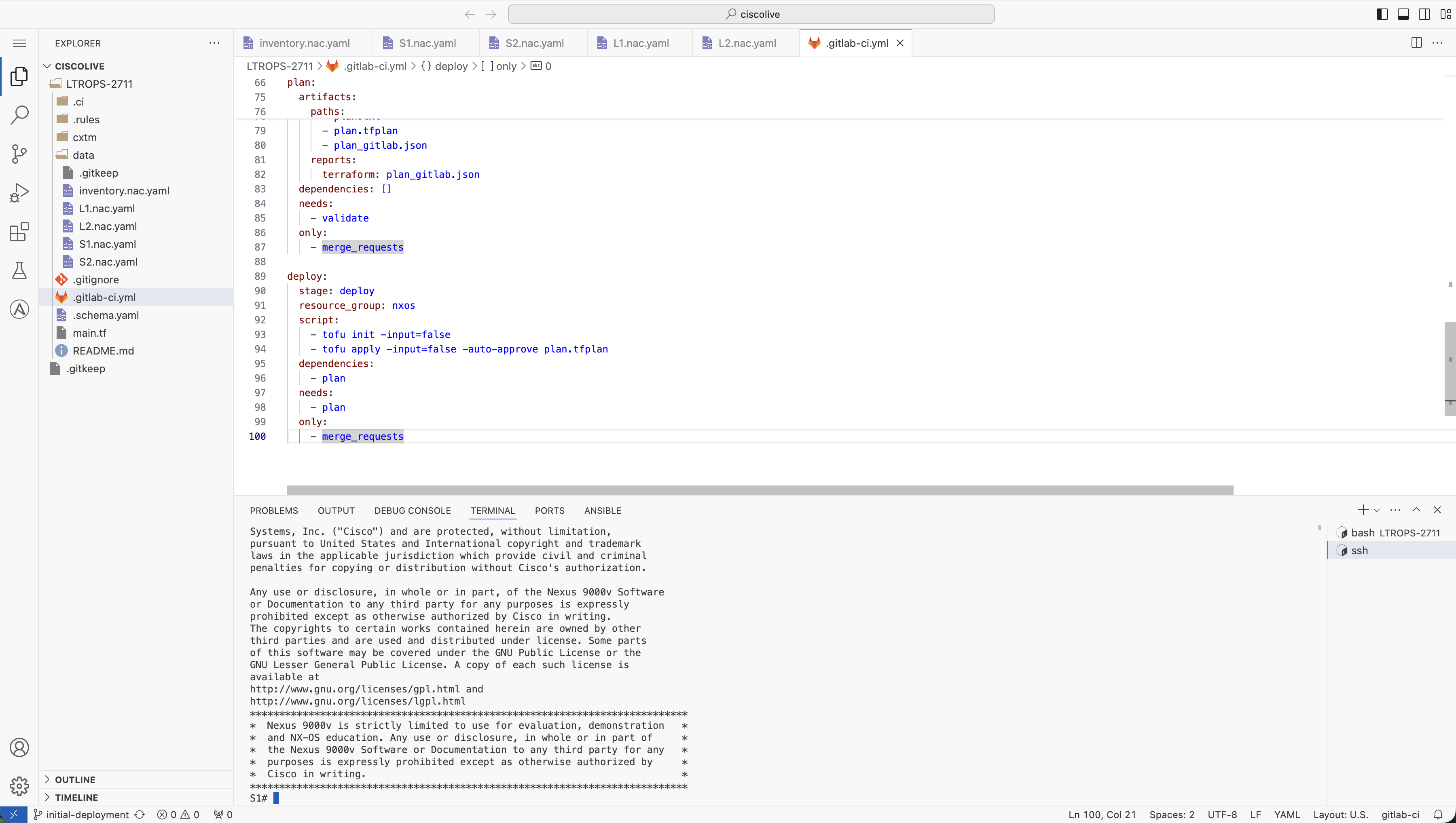
Connect to the first spine switch to verify the deployed configuration.

  1. From the VS Code Server terminal, SSH to switch S1 using the following command:

    ssh -l admin 10.15.107.21
        

  2. Enter yes to continue when prompted to confirm the SSH connection authenticity to the S1 switch.

  3. Enter the password when prompted: cisco.123

  4. You should now be successfully connected to the Spine-1 switch. Your terminal should look similar to the below:


Step 3 - Configuration Validation

Now that you are connected to the Spine-1 switch, you can validate the configuration that was deployed by the GitLab CI/CD pipeline.

  1. Verify Interface Connections by running the following command:

    show ip interface brief
        

  2. Verify the output to determine that the loopback interfaces and the connections to the leaf switches are up and running. Your output should look similar to the below output:

    IP Interface Status for VRF "default"(1)
    Interface            IP Address      Interface Status
    Lo0                  10.0.0.1        protocol-up/link-up/admin-up       
    Eth1/1               10.1.11.1       protocol-up/link-up/admin-up       
    Eth1/2               10.1.12.1       protocol-up/link-up/admin-up       
    Eth1/11              10.1.11.5       protocol-up/link-up/admin-up       
    Eth1/12              10.1.12.5       protocol-up/link-up/admin-up
        

  3. Verify BGP Connections by running the following command:

    show ip bgp summary
        

  4. Verify the output to determine that there are 4 BGP peers configured and up and running. Your output should look similar to the below output:

    BGP summary information for VRF default, address family IPv4 Unicast
    BGP router identifier 10.0.0.1, local AS number 65535
    BGP table version is 11, IPv4 Unicast config peers 4, capable peers 4
    5 network entries and 9 paths using 1884 bytes of memory
    BGP attribute entries [3/1104], BGP AS path entries [2/12]
    BGP community entries [0/0], BGP clusterlist entries [0/0]
    
    Neighbor        V    AS    MsgRcvd    MsgSent   TblVer  InQ OutQ Up/Down  State/PfxRcd
    10.1.11.2       4 65011         24         22       11    0    0 00:16:53 2         
    10.1.11.6       4 65011         24         22       11    0    0 00:16:53 2         
    10.1.12.2       4 65012         24         22       11    0    0 00:16:52 2         
    10.1.12.6       4 65012         24         22       11    0    0 00:16:53 2
        

  5. Please feel free to verify that the other switches in the deployment (S2, L1, L2) are also configured correctly by repeating the above validation steps. Exit the current switch using the exit command, then SSH to each switch using their respective IP addresses:

    • S2 (Spine-2): ssh -l admin 10.15.107.22
    • L1 (Leaf-1): ssh -l admin 10.15.107.23
    • L2 (Leaf-2): ssh -l admin 10.15.107.24